Phase 2: Sensors
Ultrasonic sound sensor is used to start making this prototype autonoumous.
The sensor is connected to the servos such that,
if the distance is less than a certain value, the servos move back.

Learning how to code and making cool things.
Combining my knowledge and experience to tackle more ambitious projects.
Ultrasonic sound sensor is used to start making this prototype autonoumous.
The sensor is connected to the servos such that,
if the distance is less than a certain value, the servos move back.
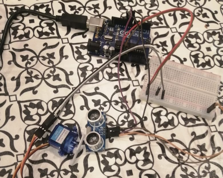
I have connected the sensor to the servo, and wrote an algorithm which detects if the distance is below a certain limit. If it is, the servo rotates from 90 degree to 0, from 0 back to 90 , then to 180 and back to 90. While this happens the sensor finds the greatest distance and then stores it:

For the final preparation, I employed a robust 4WD chassis which consists of 4 DC gearmotors, selected for their torque and efficiency, a battery holder capable of powering extended missions, sturdy tires to navigate various terrains, and the rover chassis itself, engineered for durability and stability.

After gathering all the materials, the next step was assembling everything. Initially, connecting the tires, motor, and body was crucial. Following this, the focus shifted to integrating the circuitry, which included the motor driver, Arduino, and batteries. Further steps involved testing and calibrating the components to ensure optimal functionality and performance.
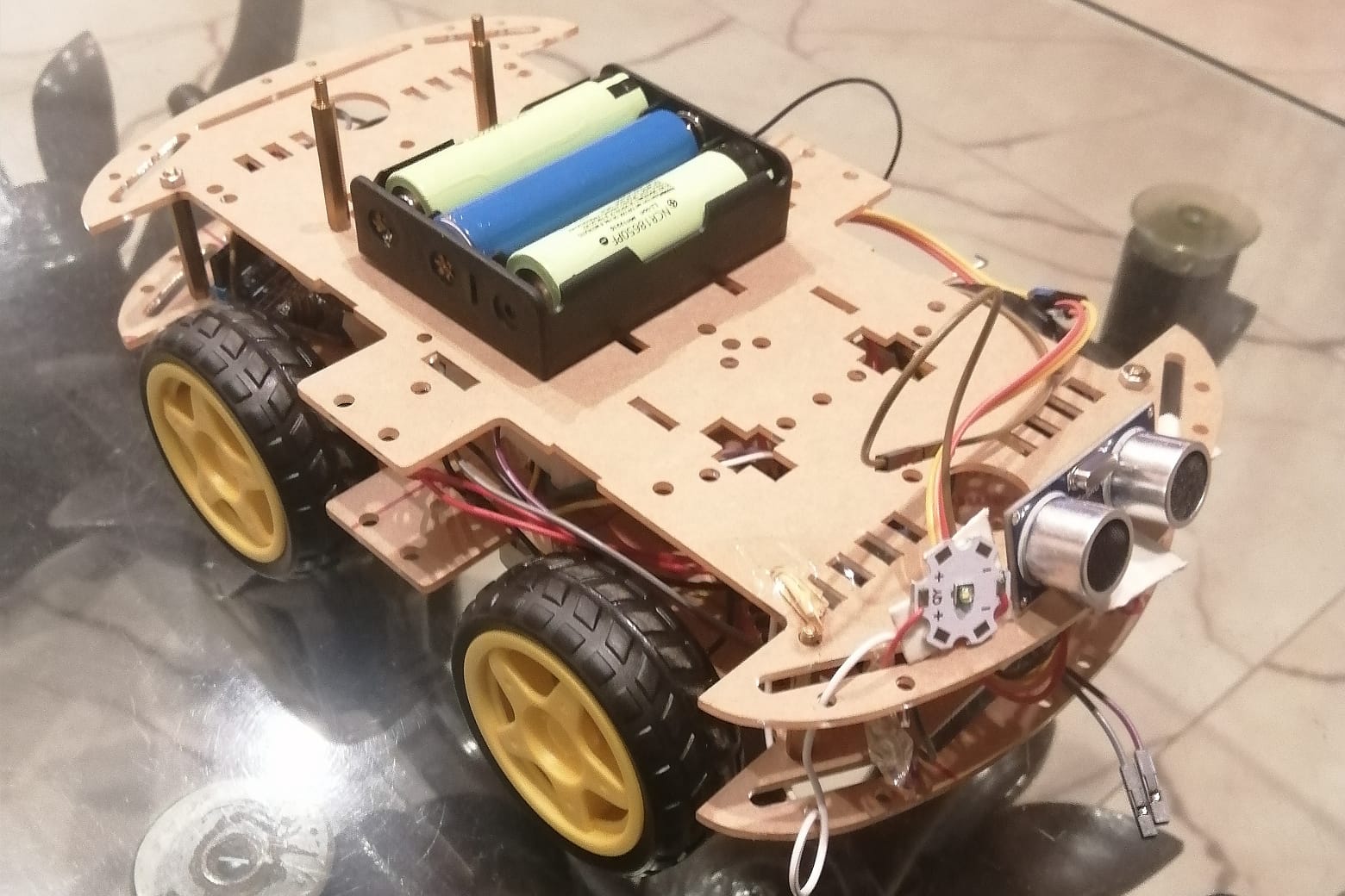
With the installation of the top chassis, including the ultrasonic sound sensor, LDR with LED, and other essential components, the rover reaches completion. Equipped with autonomous movement, automatic lighting, and recording capabilities, this rover stands fully functional and ready for its intended tasks.