PHASE-1
Phase-1 of my rover project involved gathering materials for constructing
the rover's base, as well as developing straightforward prototypes
to test and refine my initial concepts.
Gathering Materials
Arduino, micro servos, joystick, and jumper wires are the main components forming the foundation of the rover's control system. These components work together to create a versatile platform capable of various movements and functions.
The Arduino serves as the central control unit, executing commands and interfacing with other components. Micro servos are essential for controlling the rover's movement mechanisms, providing precise rotational motion based on signals received from the Arduino. The joystick acts as the rover's user interface, allowing intuitive control over its direction and speed. By manipulating the joystick, users can steer the rover in any direction and adjust its movement dynamically.
This code sets up pins for analog input (for reading X and Y axis values) and digital input (for reading a switch state), initializes a variable for position tracking, and declares four Servo objects which will control servo motors connected to the Arduino board. The specific functionality of the servo motors and how they respond to input from analog pins and the switch would be defined further in the Arduino sketch.
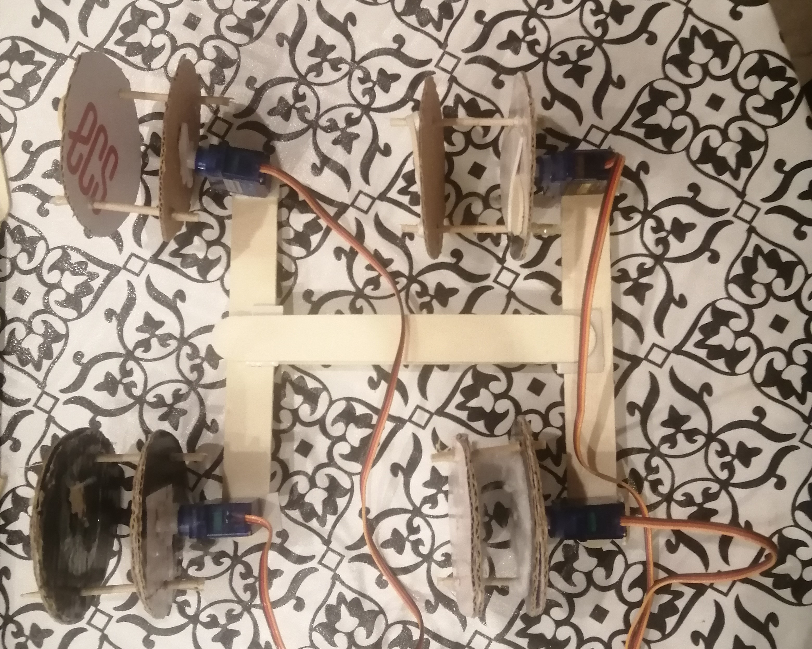
Prototype-I
The main purpose of this prototype is to evaluate and test the performance characteristics of the servo motors. By controlling the servos based on the value of x_data, the prototype aims to observe how well the servos respond to commands and whether they operate smoothly and reliably.
Design Challenges:
- Structural Integrity:
The current design lacks robustness in its structural framework. This could lead to instability or mechanical failures, especially when the servos are under load or during operation.
- Space Constraints:
There isn't sufficient space allocated for mounting the Arduino, breadboard, or other necessary components. This limitation hinders the ability to integrate and secure these components effectively within the prototype.
This code governs the movement of four servos (s1 to s4) based on the variable x_data. If x_data is 550 or higher and pos (representing servo position) is less than or equal to 180 degrees, pos is incremented by 15 degrees, and this updated position is written to all servos simultaneously. Conversely, if x_data code>is 500 or lower and pos is greater than or equal to 0, pos is decremented by 15 degrees, with the new position immediately reflected across all servos. This straightforward control mechanism ensures synchronized servo operation while maintaining position safety within standard servo limits. However, it operates within a prototype constrained by structural integrity and limited space for housing essential components like the Arduino and breadboard, highlighting potential challenges for real-world deployment.
Prototype-II
This iteration addresses the space constraint that hindered Prototype-I, allowing for better integration of components like the Arduino and breadboard. However, the ongoing challenge lies in improving the structural integrity of the design. While duct tape might humorously solve many everyday issues, it falls short when it comes to ensuring robustness in mechanical systems. Despite structural concerns, the code governing the servos remains unchanged from the previous prototype, continuing to increment or decrement servo positions based on x_data. This consistent approach ensures reliable servo control and synchronization across multiple units, contributing to the prototype's functionality despite its structural limitations.